
Kyle Rassweiler
Sunday, April 20, 2025 | 3
Networked Counter
3d printed counter using Pi5, python, pyqt6, and sqlite that can export to folders or sharepoint

Assembly CAD

Assembly CAD 2
Device Setup (Pi5+):
Base Version Part List
- 1 Raspberry Pi 5+
- 1 Raspberry Pi 5+ Power Supply
- 1 Micro SSD
- 1 Raspberry Pi 7" screen
- 1 Pi5 Diplay adapter cable
- 2 Harting Cables
- 2 M12 AMP Connector Male
- 2 M12 AMP Connector Female
- 1 Pack of jumper pin connectors
- 1 Roll of PETG filament
- 2 IR Emitter/ Receiver 5mm 3.3v
- 1 Ethernet Keystone Inline
- 1 Ethernet Patch Cable
- 1 USB C Keystone Jack Adapter USB 3.1
- 1 USB C patch cable
- 1 USB A Keystone Jack Cable
- 1 22awg Wire 2 Conductor 25ft
- 1 Rugged Metal Pushbutton - 16mm White Momentary
Stacklight Version Part List
- 1 DC Power Panel Jack
- 1 DC Power Supply
- 1 Through-Hole Resistors - 1K ohm 5% 1/4W
- 1 Through-Hole Resistors - 220 ohm 5% 1/4W
- 1 AQY210EH SSR
- 1 Tower Light - Red Yellow Green Alert Light
- 1 Tiny Premium Breadboard
Optional Parts
Pi Software
- Update system:
sudo apt update && sudo apt upgrade
- Install packages:
sudo apt install git python code wvkbd matchbox-keyboard cmake libcairo2-dev gobject-introspection libgirepository1.0-dev seahorse python3-pyqt6 python3-gpiozero python3-lgpio python3-msal python3-msal-extensions python3-dotenv
- Setup keyring for sharepoint integration:
Run seahorse and make sure there is a default keystore
- Install optional packages:
sudo apt install qtcreator sqlitebrowser
- clone repository to PI:
git clone https://github.com/rassweiler/pi-networked-counter.git && cd pi-networked-counter
- Copy the desktop file to autostart the app:
sudo cp objectcounter.desktop /etc/xdg/autostart/objectcounter.desktop
- Copy the keyboard scripts:
sudo cp toggle-keyboard.sh /usr/bin/toggle-keyboard.sh
sudo chmod +x /usr/bin/toggle-keyboard.sh
sudo cp toggle-keyboard.desktop /usr/share/raspi-ui-overrides/applications/toggle-keyboard.desktop
- Add panel icon:
mkdir -p ~/.config/lxpanel/LXDE-pi/panels/
cp /etc/xdg/lxpanel/LXDE-pi/panels/panel ~/.config/lxpanel/LXDE-pi/panels/panel
cat panel-plugin >> ~/.config/lxpanel/LXDE-pi/panels/panel
- Setup startup IO for push button:
echo "dtoverlay=gpio-poweroff,gpiopin=25,active_low" >> /boot/firmware/config.txt
Sharepoint Setup
- Create
.env.sharepointfile with access details:
AUTHORITY="https://login.microsoftonline.com/{AID}"
CLIENT_ID="{CID}"
SCOPE="User.ReadBasic.All Files.ReadWrite Sites.ReadWrite.All"
ENDPOINT="https://graph.microsoft.com/v1.0/me"
- run the
get_token.shscript once to initialise your sharepoint token, it should provide a link and a key to login using a browser.
Print Parts
- Print out the Front case section (Should contain the screen brackets as well)
- Print out the Rear case section
- Print out the Sensor case sections
- Print any required brackets/stands
Prepare Sensors
- Connect both power wires together from the IR emitter and receiver
- Connect both ground wires together from the IR emitter and receiver
- Solder the M12 AMP Connector Male to the sensors following the pinout below
Sensor Pinout To Cable
- Pin 1 (Brown): 3.3V
- Pin 2 (White): Unused
- Pin 3 (Blue): Emitter signal (Yellow)
- Pin 4 (Black): Ground
- Pin 5 (Gray): Unused
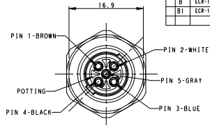
Connector Pinout

Lightstack Pinout
- Cable Brown: 12V
- Cable Green: Green LED
- Cable Yellow: Yellow LED
- Cable Red: Red LED
Pi5 Wiring
- Pin 1 (3.3V): To infeed sensor pin 1
- Pin 2 (5V): To Display pin 5 (5V)
- Pin 6 (GND): To Display pin 1 (GND)
- Pin 9 (GND): To infeed sensor pin 4
- Pin 11: To infeed sensor pin 3
- Pin 13: To stack light green wire
- Pin 14 (GND): To outfeed sensor pin 4
- Pin 15: To stack light yellow wire
- Pin 16: To outfeed sensor pin 3
- Pin 17: (3.3V): To outfeed sensor pin 1
- Pin 18: To stack light red wire
- Pin 22: To power led +
- Pin 25 (GND): To dev board for ground
- Pin 30 (GND): To power led -
Assembly Schematic
The Pi5 board is not entirely accurate, the J2 and J8 pins are proper however.
Schematic